Nov 23 2011

Troubleshoot Wireless Station Connection Issues on the FortiAP

Applies to FortiAP v4.0 MR2 and above.

These steps provide basic troubleshooting for wireless station connection issues with the FortiAP.

1. Check whether the Wireless Station entry has been created on the Access Control Wireless Controller (FortiGate). Enter the following CLI command on the FortiGate that is used for Access Control:

FG600B3909600253 # diagnose wireless-controller wlac -d sta
* vf=0 wtp=70 rId=2 wlan=open ip=0.0.0.0 mac=00:09:0f:db:c4:03 rssi=0 idle=148 bw=0 use=2
vf=0 wtp=70 rId=2 wlan=open ip=172.30.32.122 mac=00:25:9c:e0:47:88 rssi=-40 idle=0 bw=9 use=2

2. Enable the wireless MAC diagnostics filter on the Access Controller and try to determine which wireless station is failing:

FG600B3909600253 # diagnose wireless-controller wlac sta_filter 00:25:9c:e0:47:88 1
Set filter sta 00:25:9c:e0:47:88 level 1
FG600B3909600253 # 71419.245 <ih> IEEE 802.11 mgmt::disassoc <== 00:25:9c:e0:47:88 vap open rId 1 wId 0 00:09:0f:db:c4:03
71419.246 <dc> STA del 00:25:9c:e0:47:88 vap open rId 1 wId 0
71419.246 <cc> STA_CFG_REQ(34) sta 00:25:9c:e0:47:88 del ==> ws (0-192.168.35.1:5246) rId 1 wId 0
71419.246 <cc> STA del 00:25:9c:e0:47:88 vap open ws (0-192.168.35.1:5246) rId 1 wId 0 00:09:0f:db:c4:03 sec open reason I2C_STA_DEL
71419.247 <cc> STA_CFG_RESP(34) 00:25:9c:e0:47:88 <== ws (0-192.168.35.1:5246) rc 0 (Success).

3. Open a Telnet or SSH session on the FortiAP and collect the following debug. Do not use a console session.

FAP22B3U10001989 # cw_debug app cwWtpd 0x7fff

It is recommended to collect this output via Telnet or SSH rather than by using a console session. This is because using a console session could impact the performance of the device.
Once the debug has been collected then proceed to stopping the out put with the following debug command :-

FAP22B3U10001989 # cw_debug app cwWtpd 0x0

4. Collect a sniffer trace between the FortiAP and the Access Control Wireless Controller (FortiGate). The related article provides information on using the FortiOS in-built sniffer.
5. Collect a trace capturing the wireless traffic using a WiFi adaptor (For example: Airpcap or Omnipeek) and compare with the trace collected in step 4.

http://kb.fortinet.com/kb/microsites/search.do?cmd=displayKC&docType=kc&externalId=FD33214&sliceId=1&docTypeID=DT_KCARTICLE_1_1&dialogID=26359510&stateId=0%200%2026361167


Nov 23 2011

vCenter Server 4.1 network port requirements


Port Description
80 Required for direct HTTP connections. Port 80 redirects requests to HTTPS port 443.
389 Active Directory Services for the vCenter Server group
443 Listens for connections from the vSphere Client, vSphere Web Access Client, and other SDK clients.
636 SSL port of the local instance for vCenter Linked Mode.
902 UDP Used to send data to managed hosts.
902/903 Used by the vSphere Client to display virtual machine consoles.
5989 CIM transaction traffic (Hardware Status)
8080 vCenter Management Webservices HTTP.
8443 Secure connections for vCenter Management Webservices HTTPS.
60099

Used to stream inventory object changes to SDK clients. Firewall rules for this port on the vCenter Server can be set to block all, except from and to localhosts if the clients are installed on the same host as the vCenter Server service.


http://kb.vmware.com/selfservice/microsites/search.do?language=en_US&cmd=displayKC&externalId=1022256


Jul 27 2011

How to Upgrade a Juniper HA Netscreen or SSG Firewall

These notes assume that the bootloader is already up to date, and that we’re just upgrading the ScreenOS software.

Standalone Firewall

1) Download the latest ScreenOS release and release notes from Juniper support.
2) Backup (save) the config via GUI:
Configuration -> Update -> Config File -> Save to File
or Save Config via CLI: "save config to tftp ?"
3) Configuration -> Update -> Firmware/ScreenOS -> Load File. The Netscreen or SSG will now reboot and come back up at the new version.

——————————————————————-

Upgrade HA NSRP Pair – IN ATIVE/STANDBY Mode

– Upgrade Standby Unit First
– Configuration -> Update -> ScreeOS/Keys -> Firmware (ScreenOS) -> Load File -> Apply
– This will upload file, apply new image, and reboot. WebUI will time out while device is rebooting. WebUI should refresh back to Netscreen login page after it reboots – may take several minutes (after 5 min or so if it doesn’t refresh back to login page, hit the refresh button every 1-2 mins).
– Login and Confirm Home page shows new version
– Failover to secondary (On Primary: exec nsrp vsd-group 1 mode ineligible) – you can confirm group 1 is the correct VSD group through Network -> NSRP -> VSD Group
– Confirm Secondary is Master (from CLI prompt should change from (B) (backup) to (M) (master).

– Upgrade Primary
– Login to Primary Confirm home screen shows new version
– On Primary: exec nsrp sync rto all from peer (syncs objects with secondary)
– Primary may fail back to master after it upgrades/reboots (if preempt is enabled); if it does not, and secondary is still active after the primary upgrade, manually fail primary back to active/master from secondary by using: exec nsrp vsd-group 1 mode backup
——————————————————————-
Upgrade HA NSRP Pair – IN ATIVE/ACTIVE Mode
Similar to the above note, except:
Fail over master/B (Group # changes):
• If the preempt option is enabled:
exec nsrp vsd-group 1 mode ineligible
• If the preempt option is not enabled:
exec nsrp vsd-group 1 mode backup
Then fail over other device and upgrade.
Followed by SYNC: exec nsrp sync rto all
Note: Use "get nsrp" from the CLI (or viewed through the WebUI) to make sure you’re using the correct VSD group in the commands above. Also use "get system" after the upgrade to confirm the upgrade was successful and reflects the new version.

——————————————————————-
Upgrade using the CLI

To upgrade and downgrade ScreenOS via the CLI, perform the following steps:

  1. Log in to the security device using an application such as Telnet or Secure Shell (SSH) or Hyper Terminal, if directly connected through the console port. Log in as the root admin or an admin with read-write privileges.
  2. Before upgrading or downgrading a security device, save the existing configuration file to avoid losing any data:

    save config to tftp <ip_addr> <filename.cfg>
    For example:  save config to tftp 1.1.1.1 ssg5_date.cfg

    where:
    ip_addr is the IP address tftp server
    filename.cfg is the name of the Config File.

  3. For simplicity, copy the ScreenOS firmware file to the TFTP server root folder.
    Note: Important note:  Make sure that that the ScreenOS has been extracted from the ZIP folder.
  4. Start the TFTP server, by double-clicking on the TFTP server application.
  5. Save the ScreenOS firmware to flash by entering the command:

    save soft from tftp [ip_addr] [filename] to flash
    Where:
    ip_addr is the IP address of your computer
    filename is the name of the ScreenOS firmware.

    Following output is seen when the file is downloaded:

    ssg20-> save software from tftp 172.16.10.10 SSG5SSG20.5.4.0r10.0 to flash
    Load software from TFTP 172.16.10.10 (file: SSG5SSG20.5.4.0r10.0).

    !!!!!!!!!!!!!!!!!!!!!!!!!!!!!!!!!!!!!!!!!!!!!!!!!!!!
    !!!!!!!!!!!!!!!!!!!!!!!!!!!!!!!!!!!!!!!!!!!!!!!!!!!!
    !!!!!!!!!!!!!!!!!!!!!!!!!!!!!!!!!!!!!!!!!!!!!!!!!!!!
    !!!!!!!!!!!!!!!!!!!!!!!!!!!!!!!!!!!!!!!!!!!!!!!!!!!!
    !!!!!!!!!!!!!!!!!!!!!!!!!!!!!!!!!!!!!!!!!!!!!!!!!!!!

    tftp received octets = 12427198
    tftp success!
    TFTP Succeeded
    Save to flash. It may take a few minutes ...platform = 20, cpu = 1, version = 18
    update new flash image (04aa4020,12427198)
    platform = 20, cpu = 1, version = 18
    offset = 20, address = 8000000, size = 12427120
    date = 71e0f038, sw_version = 71e0f03c, cksum = 41d65212
    software major version is not same, accept this firmware? y/[n] y <==== Enter Y here
    Program flash (12427198 bytes) ...
    ++++++++++++++++++++++++++++++++++++++++++++++++++done
    Done
    ssg20->

  6. When the upgrade or downgrade is complete, you must reset the security device.   Execute the reset command and enter y at the prompt to reset the device
    ssg20-> reset <<=========Reboot the firewall using 'reset' command
    System reset, are you sure? y/[n] y <<===Enter Y here
    In reset ...

  7. Wait a few minutes, and then log in to the security device again.
  8. Use the command 'get system' to verify the version of the security device ScreenOS firmware.
  9. Use the command ‘get config‘ to review the configuation.
  10. (Not required) If the existing configuration is incorrect, which can happen on a downgrade, upload the configuration file that you saved in step 3 by executing the command:
    save config to flash from tftp <ip_addr> <filename>

    Then execute the reset command and enter n at the prompt to save the config:

    ssg20-> reset <<=========Reboot the firewall using 'reset' command
    ssg20> Configuration modified, save? [y]/n n   <<=========Enter 'n'; otherwise you will overwrite the configuration you just copied to flash
    System reset, are you sure? y/[n] y <<===Enter Y here
    ssg20-> reset

    Wait a few minutes, and then log in to the security device again.
    Note:  If you inadvertantly entered y at the ‘Configuration modified, save?’ prompt, then simply repeat step 10 and enter n.

Also see:  http://kb.juniper.net/index?page=content&id=KB13672&pmv=print


Jun 14 2011

Windows MTU Size

How to check Windows MTU size

To check the Vista MTU settings, open cmd.exe Run as Admistrator. Then type the following command:

netsh interface ipv4 show subinterface

It will display the result like below.
MTU MediaSenseState Bytes In Bytes Out Interface
—— ————— ——— ——— ————-
4294967295 1 0 40265 Loopback Pseudo-Interface 1
1300 2 91588 17394 Wireless Network Connection
1300 1 474010728 227948381 Local Area Connection


How to set Windows MTU size

To reset Vista MTU size, open command prompt as administrator and the use this following command
"netsh interface ipv4 set subinterface "Connection name" mtu=#### store=persistent"

For example the "Connection name" is Wireless Network Connection, the mtu #### is 1500, you will do: netsh interface ipv4 set subinterface "Wireless Network Connection" mtu=1500store=persistent.


Jun 10 2011

L2TP Over a NAT/VPN Device

By default, Windows XP SP2 no longer supports IPsec NAT-T security associations to servers that are located behind a network address translator. Therefore, if your virtual private network (VPN) server is behind a network address translator, by default, a Windows XP SP2-based VPN client cannot make a L2TP/IPsec connection to the VPN server. This scenario includes a VPN server that is running Microsoft Windows Server 2003.

This default behavior can also prevent computers that are running Windows XP SP2 from making Remote Desktop connections with L2TP/IPsec when the destination computer is located behind a network address translator.

Because of the way that network address translators translate network traffic, you may experience unexpected results when you put a server behind a network address translator and then use IPsec NAT-T. Therefore, if you require IPsec for communication, we recommend that you use public IP addresses for all servers that you can connect to directly from the Internet.

To create and configure the AssumeUDPEncapsulationContextOnSendRule registry value, follow these steps:

1. Click Start, click Run, type regedit, and then click OK.

2. Locate and then click the following registry subkey:

HKEY_LOCAL_MACHINE\SYSTEM\CurrentControlSet\Services\IPsec

3. On the Edit menu, point to New, and then click DWORD Value.

4. In the New Value #1 box, type AssumeUDPEncapsulationContextOnSendRule, and then press ENTER.

5. Right-click AssumeUDPEncapsulationContextOnSendRule, and then click Modify.

6. In the Value Data box, type one of the following values:

  • 0 (default)
    A value of 0 (zero) configures Windows so that it cannot establish security associations with servers that are located behind network address translators.
  • 1
    A value of 1 configures Windows so that it can establish security associations with servers that are located behind network address translators.
  • 2
    A value of 2 configures Windows so that it can establish security associations when both the server and the Windows XP SP2-based client computer are behind network address translators.

7. Click OK, and then quit Registry Editor.

8. Restart the computer.


Jun 10 2011

L2TP Split Tunneling Control

The default behavior for a Microsoft L2TP VPN add a new default route for the VPN connection and modifies the existing default route to have a higher metric, this causes all traffic to be forced through the VPN Tunnel.  You have a couple of option depending on what the clients need to actually access.

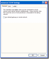
1. To access only devices on the VPN destination subnet over the tunnel you can disable the “Use default gateway on remote network” option.  Select Internet Protocol (TCP/IP) on the Networking tab for the properties of the VPN connection. Click Properties, and then click Advanced. In Advanced TCP/IP Settings, on the General tab, clear the Use default gateway on remote network check box.

clip_image001

2. If additional network need to be reachable you can add manual routes using a .cmd file or other method.  The route commands need to use the IP address that is dynamically assigned during the connection to the VPN client computer (by the VPN server) as the gateway IP address.

Example Command: route add 10.0.0.0 mask 255.0.0.0 [Client IP]

Split-tunneling Security Issues

When a VPN client computer is connected to both the Internet and a private intranet and has routes that allow reachability to both networks, the possibility exists that a malicious Internet user might use the connected VPN client computer to reach the private intranet through the authenticated VPN connection. This is possible if the VPN client computer has IP routing enabled. IP routing is enabled on Windows XP-based computers by setting the HKEY_LOCAL_MACHINE\SYSTEM\CurrentControlSet\ Services\Tcpip \Parameters\IPEnableRouter registry entry to 1 (data type is REG_DWORD).

If you must use split tunneling, you can help prevent unwanted traffic from the Internet by doing the following:

Use the Network Access Quarantine Control feature in Windows Server 2003 to check whether connecting VPN clients have IP routing enabled and, if so, do not allow VPN access until it has been disabled.   Use IP packet filters on the VPN remote access policy profile to discard both inbound traffic on the VPN connection that has not been sent from the VPN client and outbound traffic that is not destined to the VPN client. The default remote access policy named Connections to Microsoft Routing and Remote Access server in Windows Server 2003 has these packet filters configured by default.


Jun 10 2011

FortiGate Application Control Policy Not Applied

Clear all existing sessions on the firewall after having configured the new application control policy.  A session will continue to work if it was established before the policy was enabled.

Run from CLI :

diagnose sys session clear

or reboot the FortiGate.


Feb 2 2011

Chemistry Add-in for Word

http://chem4word.codeplex.com/

Version 1.0 release

We are launching the Chemistry Add-in for Microsoft Word v. 1.0 on 1 February 2011 and are also pleased to announce that we have become part of the Outercurve Foundation (http://www.outercurve.org/) in theresearch accelerators gallery.

The release version of the program is available from the downloads page along with the source code as a .ZIP package. The source code is also available under mercurial from the Source Code tab. Since our beta release in March 2010 we have been making several usability improvements including an improved 2D editor, some bug fixes, and also a completely refactored codebase. The package names have been changed to better reflect what they are doing, we have added new packages and we have moved various pieces of code (for example the navigator) from one package to another.

Introduction

The Chem4Word Project (http://research.microsoft.com/chem4word) began in 2008 as a collaboration between Microsoft Research and the University of Cambridge, designed to make it easier to insert and modify chemical information (labels, formulas, 2-D depictions, etc.) from within Microsoft Office Word, and also to have the chemical information stored and manipulated in a semantically rich manner.

On March 22, 2010, at the ACS meeting in San Francisco, CA, we announced the availability of a beta build, and we are now launching Chem4Word as an open source project overseen by Dr Joe Townsend.


Feb 1 2011

Graceful shutdown of IBM iSeries using native shutdown attaching to APC Smart-UPS

For graceful shutdown of iSeries using native shutdown attaching to Smart-UPS starting with prefix SU, SUA, SURT, and Martix 3000, 5000, or Symmetra you will need one of the serial cables listed in knowledge base 1031.

For Smart-UPS that start with prefix SMT, SMX, or SURTD along with the serial cable you will also need communications card AP9620 to establish communications from the UPS to the iSeries. See knowledge base document 11007.

APC SKU number 940-0006 actually contains two interface cables for the IBMAS/400 series:

1. APC part# 940-0006a (15-pin male cable) used with the older AS/400 9402 and 9404 models.

2. APC part# 940-0031a (9-pin male cable) used with the older AS/400 9406 and all of the newer 9402 and 9406* models.

*The i5 models are not supported with the 940-0006a cable. The i5 models need cables AP98274 or 940-0031a i5 Power 5/6/7 would use cable AP98274